Rockwell-automation 1394-SR10A External Shunt Resistor Kit User Manual
Browse online or download User Manual for Equipment Rockwell-automation 1394-SR10A External Shunt Resistor Kit. Rockwell Automation 1394-SR10A External Shunt Resistor Kit User Manual
- Page / 6
- Table of contents
- BOOKMARKS
Summary of Contents
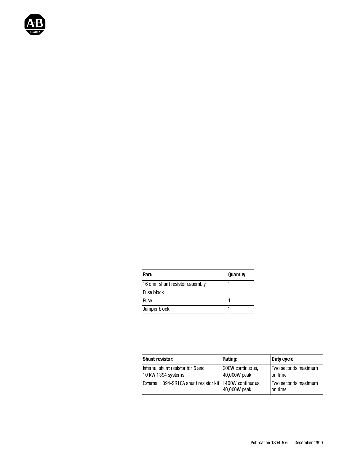
Installation Instructions1394 External Shunt Resistor Kit(Catalog Number 1394-SR10A)IntroductionThis publication provides the information necessary to
DimensionsThe dimensions of the 1394-SR10A shunt resistor assembly and fuse block are shown in the figure below.Mounting Your External Shunt ResistorT
3. Using two M10 (3/8 in.) bolts, mount the shunt resistor assembly vertically on a flat rigid metal surface that will not be subjected to shock, vibr
3. Install the jumper block in the P1 position, which is located directly behind the Status LED, as shown in Figure 3.4. Install and tighten the resis
Wiring Your External Shunt Resistor (Series C)1. Locate and unplug the J11 connector on the bottom of the system module.2.Remove and discard the jumpe
Publication 1394-5.6 — December 1999 74102-202-03(01)Supersedes Publication 1394-5.6 — February 1999 © 1999 Rockwell International. All Rights Reserv
Related products and manuals for Equipment Rockwell-automation 1394-SR10A External Shunt Resistor Kit


 (6 pages)
(80 pages)
(96 pages)
(5 pages)
(66 pages)
(2 pages)
(8 pages)
(8 pages)
(156 pages)
(34 pages)
(6 pages)
(80 pages)
(96 pages)
(5 pages)
(66 pages)
(2 pages)
(8 pages)
(8 pages)
(156 pages)
(34 pages)
© 2020, manymanuals.com. All rights reserved. | 1.476 s |
 Manymanuals.com
 Manymanuals.de
 Manymanuals.fr
 Manymanuals.it
 Manymanuals.pl
 Manymanuals.cz
 Manymanuals.es
 Manymanuals-pt.com
Comments to this Manuals