Rockwell-automation 284A ArmorStart with ArmorPoint Backplane - Gettin User Manual
Browse online or download User Manual for Equipment Rockwell-automation 284A ArmorStart with ArmorPoint Backplane - Gettin. Rockwell Automation 284A ArmorStart with ArmorPoint Backplane - Getting Started User Manual
- Page / 40
- Table of contents
- TROUBLESHOOTING
- BOOKMARKS
- ARMORSTART 1
- DISTRIBUTED 1
- MOTOR CONTROLLER WITH 1
- ARMORPOINT 1
- BACKPLANE 1
- Conduit Entrance 3
- 4 4
- ArmorConnect™ Connectivity 5
- 6 6
- Specifications 7
- Description 9
- Enclosure 10
- 11 11
- ArmorConnect Cable Ratings 12
- Three-Phase Power Media 12
- 13 13
- AC Supply Considerations 14
- ATTENTION 15
- EMI filter installed 15
- 16 16
- 17 17
- 18 18
- Theory of Operation 19
- I/O Tree Overview 20
- Logic Configuration Details 21
- 22 22
- Figure 19 String Browser Box 23
- Figure 20 String Browser Box 23
- Figure 21 Data Array 24
- Triggering a System Wide Read 25
- Interpreting the Error Report 26
- Bulletin 284 Pararmeters 27
- IMPORTANT 28
- Quick Reference 29
- Troubleshooting 29
- Fault LED Indications for 30
- Bulletin 284A ArmorStart 30
- Distributed Motor Controllers 30
- Internal Drive Faults 31
- …10V Analog 33
- Table 11 DeviceNet Media 34
- Table 12 ArmorPoint Media 34
- Table 13 Sensor Media 35
- Table 14 Sealing Caps 35
- Table 15 Digital I/O Products 36
- Table 17 Analog Products 36
- Table 20 Specialty Products 37
- Table 21 Adapter Products 38
- Registered Trademark List 40
- Trademark List 40
Summary of Contents
QUICK STARTARMORSTART® DISTRIBUTED MOTOR CONTROLLER WITH ARMORPOINT® BACKPLANEGetting StartedBULLETIN 284AIntroductionThis guide provides the basic in
10 Publication 284A-QS001C-EN-P - July 2006Figure 7 Control Power Media System Overview➏ Control Power Media Patchcords - PatchCord cable with
Publication 284A-QS001C-EN-P - July 2006 11ArmorStart with ArmorConnect ConnectivityInstalling ArmorConnect Power Media using Cord GripsContro
12 Publication 284A-QS001C-EN-P - July 2006ArmorConnect Cable RatingsThe ArmorConnect Power Media cables are rated per UL Type TC 600V 90 °C Dr
Publication 284A-QS001C-EN-P - July 2006 13Group Motor Installations for USA and Canada MarketsThe ArmorStart Distributed Motor controllers are
14 Publication 284A-QS001C-EN-P - July 2006meant to be unplugged and replaced after proper lockout/tag-out procedures have been employed.Since
Publication 284A-QS001C-EN-P - July 2006 15Figure 8 Removal of Control ModuleFigure 9 Jumper RemovalRemove JumperATTENTION!Do not remove this j
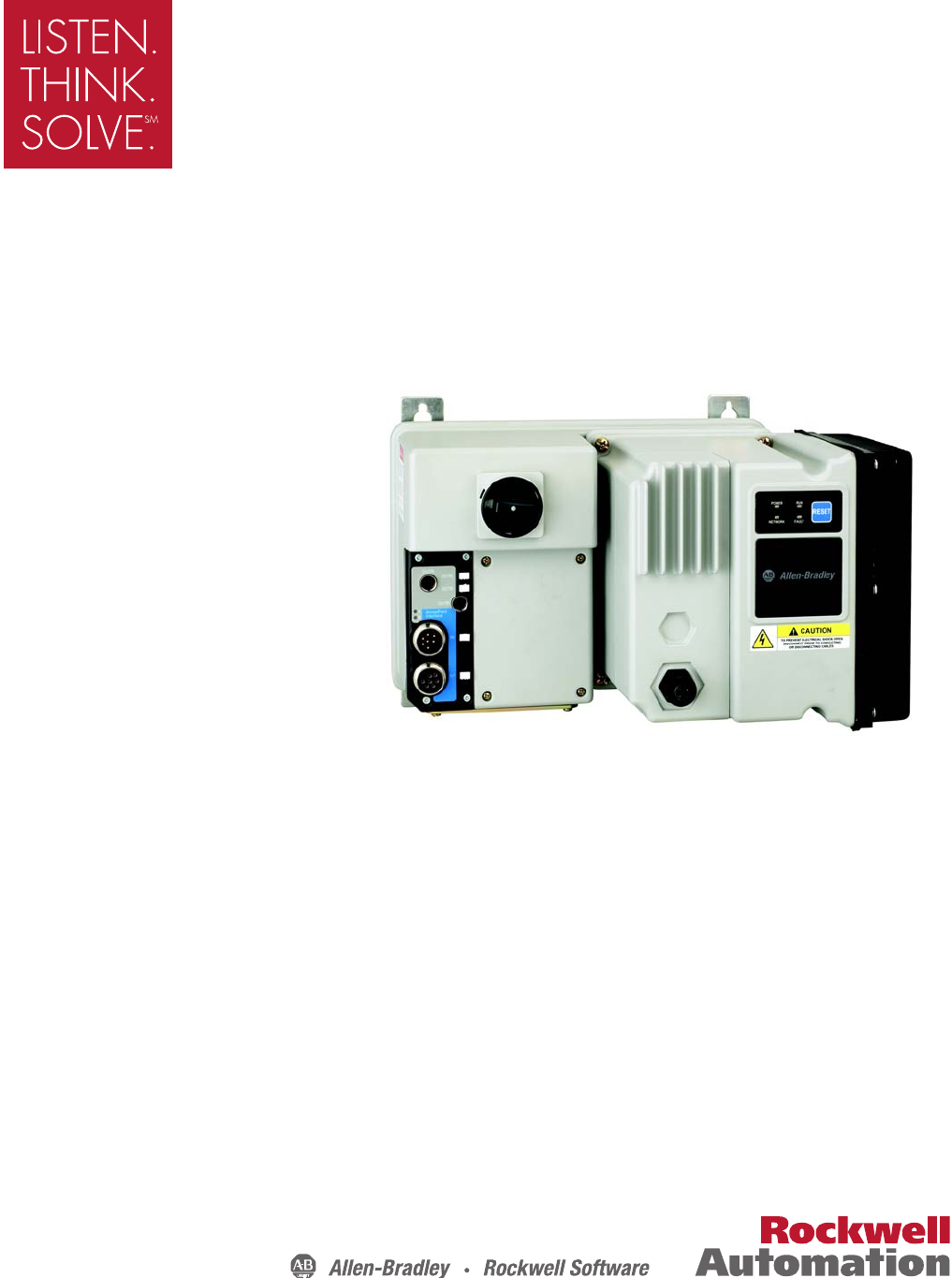
16 Publication 284A-QS001C-EN-P - July 2006LED Status Indication The LED Status Indication provides 4 status LEDs and a Reset button. The LEDs
Publication 284A-QS001C-EN-P - July 2006 17When connecting to the Bulletin 1738 ArmorPoint Distributed I/O product, a network adapter and at le
18 Publication 284A-QS001C-EN-P - July 2006Details on Using the “ArmorStart Ladder Logic Configurator”The ArmorStart Ladder Logic Configurator
Publication 284A-QS001C-EN-P - July 2006 19Theory of OperationIt is possible to connect an ArmorStart product to the Point I/O based subnet of
20 Publication 284A-QS001C-EN-P - July 2006I/O Tree OverviewIn order to transfer I/O information, the ArmorStart needs to be added to the I/O t
Publication 284A-QS001C-EN-P - July 2006 21Logic Configuration DetailsInside the Configurator file is a large User Defined structure called Arm
22 Publication 284A-QS001C-EN-P - July 2006Figure 17 Array Size Parameter Armor_Start_System.Num_Devices defaults to zero and is defined as the
Publication 284A-QS001C-EN-P - July 2006 23Figure 18 Communication Card ConfigurationNote: To easily edit an ASCII string, click on the strin
24 Publication 284A-QS001C-EN-P - July 2006modified. The parameter numbers all start with 1 and are numbered sequentially to the last parameter
Publication 284A-QS001C-EN-P - July 2006 25Triggering a System Wide ReadOnce the system configuration has been done, a System Wide Read must be
26 Publication 284A-QS001C-EN-P - July 2006Interpreting the Error ReportIf an error occurs during the operation of the ladder logic, either the
Publication 284A-QS001C-EN-P - July 2006 27Bulletin 284 PararmetersTable 4 Basic Program Group for Sensorless Vector Performance➊ Stop drive be
28 Publication 284A-QS001C-EN-P - July 2006Table 5 Basic Program Group for Sensorless Vector Control➊ Stop drive before changing this parameter
Publication 284A-QS001C-EN-P - July 2006 29Quick Reference TroubleshootingThere are four LEDs on the front of the ArmorStart that can provide a
Publication 284A-QS001C-EN-P - July 2006 3Installation The ArmorStart Distributed Motor Controller is convection cooled. Operating temperature
30 Publication 284A-QS001C-EN-P - July 2006Fault LED Indications for Bulletin 284A ArmorStart Distributed Motor ControllersTable 8 Controller F
Publication 284A-QS001C-EN-P - July 2006 31Internal Drive FaultsA fault is a condition that stops the drive. There are two fault types.Table 9
32 Publication 284A-QS001C-EN-P - July 2006Table 10 Fault Types, Descriptions, and Actions➊ See Table 9 for internal drive fault types.No. Faul
Publication 284A-QS001C-EN-P - July 2006 33Table 10 Fault Types, Descriptions, and Actions (Continued)➊ See Table 9 for internal drive fault
34 Publication 284A-QS001C-EN-P - July 2006Accessories Table 11 DeviceNet Media ➊➊See publication M116-CA001A-EN-P for complete cable selection
Publication 284A-QS001C-EN-P - July 2006 35Table 13 Sensor Media ➊ ➊See Publication M116-CA001A-EN-P for complete cable selection information.➋
36 Publication 284A-QS001C-EN-P - July 2006Bulletin 1738 ArmorPoint Distributed I/O ProductsTable 15 Digital I/O ProductsTable 16 Digital Input
Publication 284A-QS001C-EN-P - July 2006 37Table 18 Power Supply ProductsTable 19 AC and Relay ProductsTable 20 Specialty ProductsDescription C
38 Publication 284A-QS001C-EN-P - July 2006Table 21 Adapter ProductsDescription Cat. No.0ArmorPoint DeviceNet Adapter Module, Drop or Pass-thro
4 Publication 284A-QS001C-EN-P - July 2006Dimensions are shown in millimeters (inches). Dimensions are not intended to be used for manufacturin
Publication 284A-QS001C-EN-P — July 2006 41053-384-04Superecedes Publication 284A-QS001B-EN-P — September 2005 Copyright ©2006 Rockwell Automation, In
Publication 284A-QS001C-EN-P - July 2006 5Dimensions are shown in millimeters (inches). Dimensions are not intended to be used for manufacturin
6 Publication 284A-QS001C-EN-P - July 2006Dimensions are shown in millimeters (inches). Dimensions are not intended to be used for manufacturin
Publication 284A-QS001C-EN-P - July 2006 7Wiring Power, Control, Safety Monitor Inputs, and Ground Wiring Table 1 provides the power, control,
8 Publication 284A-QS001C-EN-P - July 2006Table 2 Power, Control, and Ground Terminal Designations➊ Only available with the Safety Monitor opti
Publication 284A-QS001C-EN-P - July 2006 9ArmorConnect Power Media DescriptionThe ArmorStart Power Media offers both three-phase and control po
Related products and manuals for Equipment Rockwell-automation 284A ArmorStart with ArmorPoint Backplane - Gettin
 (4 pages)
(6 pages)
(2 pages)
(98 pages)
(4 pages)
(6 pages)
(2 pages)
(98 pages)

 (1 pages)

 (2 pages)
(1 pages)
(7 pages)
(2 pages)
(1 pages)
(7 pages)
© 2020, manymanuals.com. All rights reserved. | 1.165 s |
 Manymanuals.com
 Manymanuals.de
 Manymanuals.fr
 Manymanuals.it
 Manymanuals.pl
 Manymanuals.cz
 Manymanuals.es
 Manymanuals-pt.com
Comments to this Manuals